Types of transformers
A transformer is a static electromagnetic device containing two to several coils located on a common magnetic circuit and thus inductively connected to each other. It serves as a transformer to convert electrical energy from alternating current by means of electromagnetic induction without changing the frequency of the current. Transformers are used for both AC voltage conversion and galvanic isolation in various fields of electrical and electronics engineering.
In fairness, we note that in some cases the transformer may contain only one winding (autotransformer), and the core may be completely absent (HF — transformer), but most of the transformers have a core (magnetic circuit) made of soft magnetic ferromagnetic material, and two or more insulated tape or wire coils covered by a common magnetic flux, but first in the first place. Let's look at what types of transformers they are, how they are arranged and what they are used for.
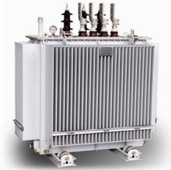
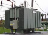
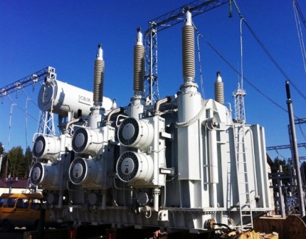
Power transformer
This type of low-frequency (50-60 Hz) transformers is used in electrical networks, as well as in installations for receiving and converting electrical energy. Why is it called power? Because it is this type of transformer that is used to supply and receive electricity from and from power lines, where the voltage can reach 1150 kV.
In urban electrical networks, the voltage reaches 10 kV. Through exactly powerful low-frequency transformers the voltage also drops to the 0.4 kV, 380/220 volts required by consumers.
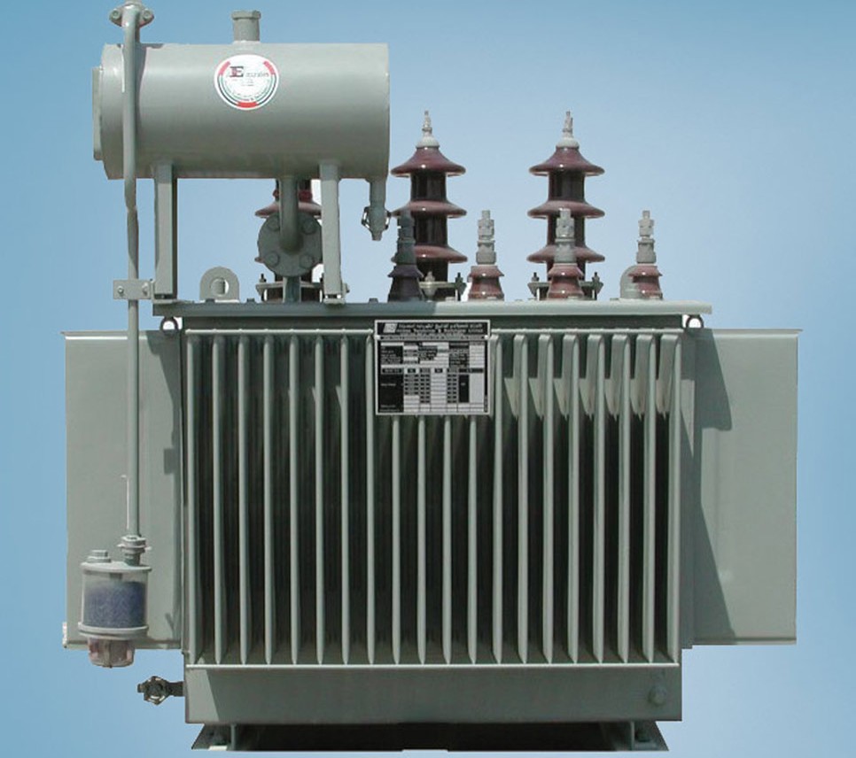
Structurally, a typical power transformer may contain two, three or more windings arranged on an armored electrical steel core, with some of the low-voltage windings fed in parallel (split-winding transformer).
This is useful for boosting the voltage received from multiple generators simultaneously. As a rule, the power transformer is placed in a tank with transformer oil, and in the case of particularly powerful specimens, an active cooling system is added.
Three-phase power transformers with a capacity of up to 4000 kVA are installed at substations and power plants. Three-phase are more common, as losses are obtained up to 15% less than with three single-phase.
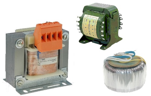
Mains transformer
In the 1980s and 1990s, line transformers could be found in almost every electrical appliance. With the help of a mains transformer (usually single-phase), the voltage of a 220 volt household network with a frequency of 50 Hz is reduced to the level required by an electrical appliance, for example 5, 12, 24 or 48 volts.
Line transformers are often made with multiple secondary windings so that multiple voltage sources can be used to power different parts of the circuit. In particular, TN (incandescent transformer) transformers could always (and still can) be found in circuits where radio tubes are present.
Modern line transformers are constructed on W-shaped, rod-shaped or toroidal cores of a set of electrical steel plates on which the windings are wound. The toroidal shape of the magnetic circuit makes it possible to obtain a more compact transformer.
If we compare transformers with the same total power of toroidal and W-shaped cores, the toroidal will take up less space, in addition, the surface of the toroidal magnetic circuit is completely covered by the windings, there is no empty yoke, as is the case with armored W-shaped or rod-like nuclei. The electrical network includes, in particular, welding transformers with a power of up to 6 kW. Mains transformers are, of course, classified as low-frequency transformers.
Autotransformer
One type of low-frequency transformer is an autotransformer in which the secondary winding is part of the primary or the primary is part of the secondary. That is, in the autotransformer, the windings are connected not only magnetically, but also electrically. Several leads are made from one coil and allow you to get different voltages from just one coil.
The main advantage of the autotransformer is its lower cost, since less wire is used for the windings, less steel for the core, and as a result the weight is less than that of a conventional transformer.The disadvantage is the lack of galvanic isolation of the coils.
Autotransformers are used in automatic control devices and are also widely used in high-voltage electrical networks. Three-phase autotransformers with delta or star connection in electrical networks are in great demand today.
Power autotransformers are available in capacities up to hundreds of megawatts. Autotransformers are also used to start powerful AC motors. Autotransformers are particularly useful for low transformation ratios.
Laboratory autotransformer
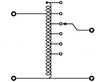
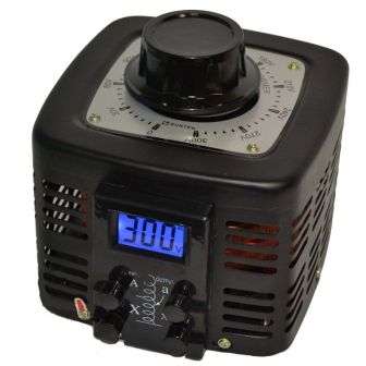
A special case of an autotransformer is a laboratory autotransformer (LATR). It allows you to smoothly adjust the voltage supplied to the user. The LATR design is toroidal transformer with a single winding that has an uninsulated "track" from turn to turn, that is, it is possible to connect to each of the turns of the winding. Track contact is provided by a sliding carbon brush that is controlled by a rotary knob.
So you can get the effective voltage with different magnitudes on the load. Typical single-phase drives allow you to accept voltages from 0 to 250 volts, and three-phase - from 0 to 450 volts. LATRs with power from 0.5 to 10 kW are very popular in laboratories for the purpose of tuning electrical equipment.
Current transformer
Current transformer is called a transformer whose primary winding is connected to a source of current and the secondary winding to protective or measuring devices that have low internal resistance. The most common type of current transformer is an instrument current transformer.
The primary winding of the current transformer (usually only one turn, one wire) is connected in series in the circuit in which you want to measure the alternating current. It turns out that the current of the secondary winding is proportional to the current of the primary, while the secondary winding must necessarily be loaded, because otherwise the voltage of the secondary winding can be high enough to break the insulation. Also, if the secondary winding of the CT opens, the magnetic circuit will simply burn out from the induced uncompensated currents.
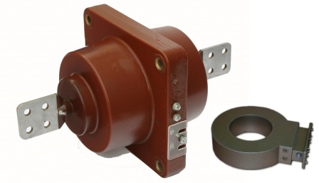
The construction of the current transformer is a core made of laminated silicon cold-rolled electrical steel on which one or more insulated secondary windings are wound. The primary winding is often simply a busbar or wire with a measured current passed through the window of the magnetic circuit (by the way, this principle is used by clamp meter).The main characteristic of a current transformer is the transformation ratio, for example 100/5 A.
Current transformers are widely used for current measurement and in relay protection circuits. They are safe because the measured and secondary circuits are galvanically isolated from each other. Typically, industrial current transformers are manufactured with two or more groups of secondary windings, one of which is connected to protective devices, the other to a measuring device, such as meters.
Pulse transformer
In almost all modern mains power supplies, in various inverters, in welding machines and in other power and low-power electrical converters, pulse transformers are used.Today, pulse circuits have almost completely replaced heavy low-frequency transformers with laminated steel cores.
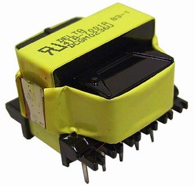
A typical pulse transformer is a ferrite core transformer. The shape of the core (magnetic circuit) can be completely different: ring, rod, cup, W-shaped, U-shaped. The advantage of ferrites over transformer steel is obvious — ferrite-based transformers can operate at frequencies up to 500 kHz or more.
Since the pulse transformer is a high-frequency transformer, its dimensions are reduced significantly as the frequency increases. Less wire is required for the windings and the field current is sufficient to obtain a high frequency current in the primary loop, IGBT or a bipolar transistor, sometimes several, depending on the topology of the pulsed power supply circuit (forward — 1, push-pull — 2, half-bridge — 2, bridge — 4).
To be fair, we note that if a reverse power supply circuit is used, then the transformer is essentially a double choke, since the processes of accumulation and release of electricity in the secondary circuit are separated in time, that is, they do not proceed simultaneously, therefore, with flyback control circuit, it is still a choke but not a transformer.
Pulse circuits with transformers and ferrite chokes are found everywhere today, from ballasts of energy-saving lamps and chargers of various gadgets, to welding machines and powerful inverters.
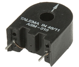
Pulse current transformer
To measure the magnitude and (or) direction of current in impulse circuits, impulse current transformers are often used, which are a ferrite core, often ring-shaped (toroidal), with one winding.A wire is passed through the ring of the core, the current in which is to be examined, and the coil itself is loaded on a resistor.
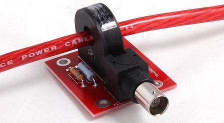
For example, the ring contains 1000 turns of wire, then the ratio of the currents of the primary (threaded wire) and the secondary winding will be 1000 to 1. If the winding of the ring is loaded on a resistor of a known value, then the voltage measured across it will be proportional to the current of the coil, which means that the measured current is 1000 times the current through this resistor.
The industry produces impulse current transformers with different transformation ratios. The designer only needs to connect a resistor and a measuring circuit to such a transformer. If you want to know the direction of the current, not its magnitude, then the winding of the current transformer is simply charged by two opposing zener diodes.
Communication between electrical machines and transformers
Electrical transformers are always included in the electrical machine courses studied in all electrical engineering specialties of educational institutions. In essence, an electric transformer is not an electric machine, but an electric apparatus, since there are no moving parts, the presence of which is a characteristic feature of any machine as a type of mechanism. For this reason, the mentioned courses, in order to avoid misunderstandings, should be called "electrical machines and electrical transformers courses".
The inclusion of transformers in all electrical machinery courses is for two reasons.One is of historical origin: the same factories that built AC electrical machines also built transformers, because the mere presence of transformers gave AC machines an advantage over DC machines, which ultimately was led to their predominance in the industry. And now it is impossible to imagine a large AC installation without transformers.
However, with the development of the production of alternating current machines and transformers, it became necessary to concentrate the production of transformers in special transformer factories. The fact is that due to the possibility of transmitting alternating current using transformers over long distances, the increase in the higher voltage of transformers was much faster than the increase in voltage of alternating current electrical machines.
At the current stage of development of alternating current electrical machines, the highest rational voltage for them is 36 kV. At the same time, the highest voltage in actually implemented electric transformers reached 1150 kV. Such high transformer voltages and their operation on overhead power lines exposed to lightning have led to very specific transformer problems that are foreign to electrical machinery.
This led to the production of technological problems so different from the technological problems of electrical engineering that the separation of transformers into independent production became inevitable. Thus, the first reason—the industrial connection that made transformers close to electrical machines—disappeared.
The second reason is of a fundamental nature and consists in the fact that the electric transformers used in practice, as well as the electric machines, are based on the principle of electromagnetic induction (Faraday's law), — remains an unshakable bond between them. At the same time, in order to understand many phenomena in alternating current machines, a knowledge of the physical processes occurring in transformers is absolutely necessary, and, moreover, the theory of a large class of alternating current machines can be reduced to the theory of transformers, as thus facilitating their theoretical consideration.
Therefore, in the theory of alternating current machines, the theory of transformers occupies a strong place, from which, however, it does not follow that transformers can be called electrical machines. In addition, it should be borne in mind that transformers have a different goal setting and energy conversion process than electrical machines.
The purpose of an electrical machine is to convert mechanical energy into electrical energy (generator) or, conversely, electrical energy into mechanical energy (motor), meanwhile in a transformer we are dealing with the conversion of a type of alternating current electrical energy into alternating current electrical energy. current of a different kind.