Basic laws of electrical engineering
 OHM'S LAW (named after the German physicist G. Ohm (1787-1854)) is a unit of electrical resistance. Notation Ohm. Ohm is the resistance of the wire between the ends of which at amperage 1 A, a voltage of 1 V occurs. The governing equation for electrical resistance is R = U / I.
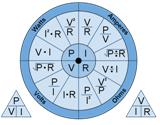
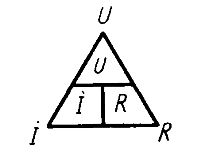
Ohm's law is the basic law of electrical engineering that cannot be neglected when calculating electrical circuits. The relationship between the voltage drop across the conductor, its resistance and the current strength is easily remembered in the form of a triangle, at the vertices of which are the symbols U, I, R.
Ohm's Law
The most important law of electrical engineering — Ohm's law
Ohm's law for a section of a circuit
Application of Ohm's law in practice
What is electrical resistance?
JOUL-LENZ LAW (named after the English physicist J.P. Joule and the Russian physicist E.H. Lenz) — the law that characterizes thermal effect of electric current.
According to the law, the amount of heat Q (in joules) released in a conductor when a direct electric current passes through it depends on the strength of the current I (in amperes), wire resistance R (in ohms) and its transit time t (in seconds): Q = I2Rt.
The conversion of electrical energy into heat is widely used in electric furnaces and various electric heating devices. The same effect in electrical machines and apparatus leads to inadvertent waste of energy (loss of energy and reduction of efficiency). The heat that causes these devices to heat up limits their load. In case of overload, the temperature increase may damage the insulation or shorten the service life of the unit.
How does an electric shock heat up a wire
How heating affects resistance value
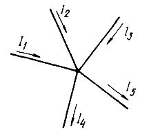
Kirchhoff's law (named after the German physicist G.R. Kirchhoff (1824-1887)) — two basic laws of electric circuits. The first law establishes a relationship between the sum of the currents directed into the node at the junction (positive) and the sum of the currents directed away from the node (negative).
The algebraic sum of the currents In converging at each point of the branch of the wire (node) is equal to zero, i.e. SUMM (In) = 0. For example, for node A, you can write: I1 + I2 = I3 + I4 or I1 + I2 — I3 — I4 = 0.
Current node
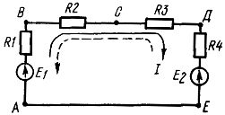
The second law establishes a relationship between the sum of electromotive forces and the sum of the voltage drop across the closed circuit resistances of an electrical circuit. Currents that coincide with an arbitrarily chosen direction of flow of the loop are considered positive, and those that do not match are considered negative.
Current cycle
The algebraic sum of the instantaneous values of EMF of all voltage sources in each circuit of the electric circuit is equal to the algebraic sum of the instantaneous values of the voltage drop in all resistances of the same circuit SUMM (En) = SUMM (InRn). Rearranging SUMM (InRn) on the left side of the equation, we get SUMM (En) — SUMM (InRn) = 0. The algebraic sum of the values of the instantaneous voltages on all elements of the closed circuit of the electric circuit is equal to zero.
FULL PRESENT LAW one of the fundamental laws of the electromagnetic field. It establishes the relationship between the magnetic force and the amount of current passing through the surface. The total current is understood as the algebraic sum of currents penetrating the surface bounded by a closed loop.
The magnetizing force along the loop is equal to the total current passing through the surface bounded by this loop. In the general case, the field strength in different sections of the magnetic line can have different values, and then the magnetizing force will be equal to the sum of the magnetizing forces on each line.
LENZ'S LAW — the basic rule covering all cases of electromagnetic induction and enabling the direction of the emerging EMF to be determined. induction.
According to Lenz's law, this direction is in all cases such that the current created by the emerging emf prevents the changes that caused the emf to appear. induction. This law is a qualitative formulation law of conservation of energy applied to electromagnetic induction.
THE LAW OF ELECTROMAGNETIC INDUCTION, Faraday's Law — the law which establishes the relation between magnetic and electrical phenomena.The EMF of the electromagnetic induction in the circuit is numerically equal and opposite in sign to the rate of change of the magnetic flux through the surface bounded by this circuit. The magnitude of the EMF field depends on the rate of change of the magnetic flux.
The law of electromagnetic induction
FARADAY'S LAWS (named after the English physicist M. Faraday (1791-1867)) — the basic laws of electrolysis.
A relationship is established between the amount of electricity passing through the electrically conductive solution (electrolyte) and the amount of substance released on the electrodes.
When a direct current I passes through the electrolyte per second, q = It, m = kIt.
Faraday's second law: the electrochemical equivalents of elements are directly proportional to their chemical equivalents.
DRILL RULE — a rule that allows you to determine the direction of the magnetic field, depending on directions of electric current… When the forward movement of the gimbal coincides with the current flowing, the direction of rotation of its handle indicates the direction of the magnetic lines. Or, if the direction of rotation of the gripping handle coincides with the direction of the current in the loop, the translational movement of the gimbal indicates the direction of the magnetic lines penetrating the surface bounded by the loop.
How the gimbal rule works in electrical engineering
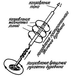
gimlet rule
LEFT-HAND RULE — a rule that allows you to determine the direction of the electromagnetic force. If the palm of the left hand is positioned so that the vector of magnetic induction enters it (the outstretched four fingers coincide with the direction of the current), then the thumb of the left hand, bent at a right angle, indicates the direction of the electromagnetic force.
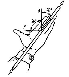
Left hand rule
RIGHT-HAND RULE — a rule that allows you to determine the direction of the induced emf of electromagnetic induction. The palm of the right hand is positioned so that the magnetic lines enter it. The thumb, bent at a right angle, is aligned with the driver's direction of travel. The extended four fingers will indicate the direction of the induced emf.
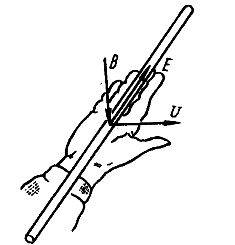
Right hand rule