Automatic control scheme for two pump units
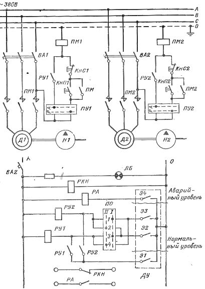
 The figure shows a diagram of the automatic control of two pumping units operating without personnel on duty.
The operation of the circuit is based on the principle of starting and stopping the pumps, depending on the liquid level in the controlled tank from which the pumping is carried out. Use to control the filling of the tank with liquid electrode level sensor DU. Of the two pump units, one is running and the other is in standby mode.
The operating mode of the blocks is set control switch (SW pumping switch): in position 1 of the switch, pump H1 with motor D1 will run, and pump H2 with motor D2 will be in standby mode, which is activated if the capacity of pump H1 is insufficient. In position 1, the working pump is H2 and the standby pump is H2.
Consider the operation of the circuit when the software switch is set to position 1 and the switches PU1 and PU2 are in position A, i.e. automatic pump control.Contacts 1 and 3 of the PO switch close the circuits of the relay coils RU1 and RU2, but the relay will not turn on, because at a normal liquid level, the electrodes E2 and EZ of the remote control level sensor remain open.
Automatic circuit for control of two evacuation pumps
When the liquid level in the container rises to the E2 electrode, the coil circuit closes intermediate relay RU1, it is triggered and through the closing contact RU1 is supplied to the starter coil PM1. Motor D1 turns on and pump H1 starts pumping.
The liquid level in the tank decreases, but when contact E2 breaks, motor D1 will not stop, because relay coil RU1 continues to receive energy through its contact RU1 and the closed contact of electrode E1. Such blocking of the RU1 relay is used to avoid frequent starts and stops of the pumping unit with small changes in the liquid level and ensures that the pump is turned off only when the liquid level falls below normal and the E1 contact opens.
If an emergency stop of the operating pump occurs or its performance is insufficient, the liquid level in the tank will continue to rise. When it reaches the EZ electrode of the remote control sensor, the relay coil RU2 will be energized. The relay will operate and turn on the magnetic starter PM2, the backup pump motor D2 will turn on. The device in standby mode will shut down when the liquid level drops below electrode A1.
If for some reason there is a large inflow of liquid into the tank, then the work of both pump units may be insufficient and the liquid will rise to the maximum permissible level at which the E4 electrode is installed. This will close the circuit of the coil of the PA relay, which will operate and with its closing contact activate the alarm circuit, notifying the personnel of the abnormal operation of the pumping units.
The voltage control relay RKN is used to provide a warning signal in the event of a voltage failure in the control circuits. The alarm circuits are powered by an independent power supply. The white signal lamp LU serves to warn of the presence of voltage in the control circuits during control checks of the equipment.
The transition to manual (local) control of the pumping units is carried out by turning the switches PU1 and PU2 to position P. Engines D1 or D2 are turned on and off by pressing the buttons KnP1 and KnS1 or KnP2 and KnS2 located directly on the pump units .
See also: Selection of power of the electric motor of the pumping unit