An intuitive method for designing control schemes
 Intuitive method — a method of developing control schemes based on the experience gained in various design organizations in the automation of various mechanisms. It is based on the designer's engineering intuition.
Only one who has absorbed all previous experience and has certain abilities in terms of drawing up schemes, who can think abstractly and reason logically, can perfectly master this method. Despite its complexity, most electrical designers use the intuitive method extensively.
For example, consider a simplified kinematic diagram of a push lever (Fig. 1). When the wheel 5 rotates clockwise, the lever 4 rotates the lever 1 about the axis O, thereby forcing the shoe 3 with the lever 2 to translate. With further rotation of the wheel 5, the direction of movement of the lever 1 changes and the shoe returns to its original position, after which the engine must stop.
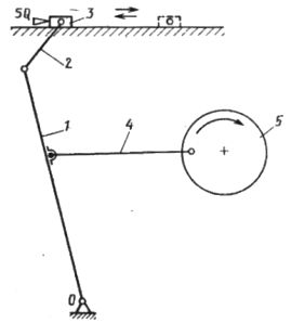
Rice. 1. Schematic diagram of the lever pusher control
The considered mechanism is a typical representative of a pushing device.In the first cycle, the mechanism is on and running. In the second measure it does not work. The cycle in which the mechanism does not work is called zero. Although the shoe is fully reciprocating (forward and backward), a non-reversible electric motor can be used for propulsion.
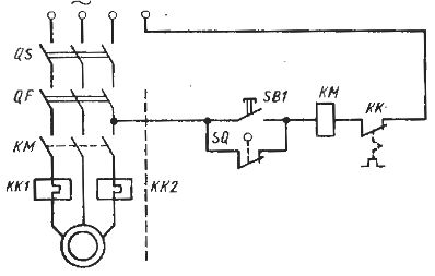
The control circuit of the lever-piston electric motor consists of two parts (in Fig. 1 they are separated by a dotted line): the power circuit and the control circuit.
Consider the purpose of the elements of the power circuit. Three-phase current is supplied to the QS switch, which cuts off the power supply to the electric motor in the event of repair or damage to the magnetic starter. Then the current flows through the circuit breaker whose QF release is shown in the diagram. It is designed to protect and disconnect the power supply to the drive in case of short circuit currents. The main contacts of the magnetic starter KM turn on or off the winding of the electric motor M.
Thermal relays KK1 and KK2, the heating elements of which are shown in the power circuits, are designed to protect the electric motor from prolonged overloads:
The control scheme works as follows. When you press the start button SB1, the coil of the magnetic starter KM is energized and therefore the contacts of the supply circuit of KM are closed and electric current enters the motor winding. The motor rotor is rotated and the drum starts to move forward. At the same time, it moves away from the lever of the limit switch SQ and its contacts are closed.
When the start button SB1 is released and its contacts open, the KM coil of the magnetic starter will receive power through the contacts of the limit switch SQ.After moving forward, and then backward, the piston will press the lever of the limit switch SQ, its contacts will open and the coil of KM will turn off. This will cause the KM contacts in the power circuit to open and stop the electric motor.
The considered circuit contains power and control circuits. In the future, only control schemes will be considered.
By function, i.e. by purpose, all elements involved in the operation of the circuit can be divided into three groups: control contacts, intermediate elements and executive elements.
Control contacts are the elements with which commands are issued (control buttons, switches, limit switches, primary converters, relay contacts, etc.).
The very name of the intermediate elements indicates that they occupy an intermediate position between the control and executive elements. In relay-contact circuits, they include time relays and intermediate relays, and in non-contact circuits — logic gates.
Executive elements are executive mechanisms. However, when developing control circuits, the drive mechanisms themselves (electric motors or heating elements) are not used, but the devices that include them, i.e. magnetic starters, contactors, etc.
All control contacts, according to their functional principle, are divided into five types: start contact with short action (PC), start contact with long action (PD), stop contact with short action (OK), stop contact with long action (OD ), start-stop contact (software). These contacts are called the main ones.
Cyclograms of the operation of all typical contacts in the control of cyclic mechanisms are shown in fig. 2.
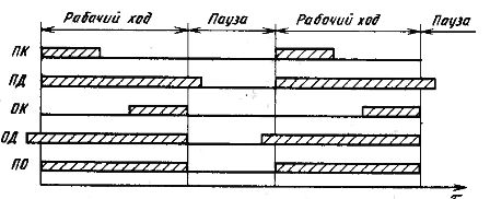
Rice. 2.Cyclogram of control contacts
Each of the five contacts starts working (closes) and ends (opens) at specific moments in time. So, the start contacts start their work together with the beginning of the working stroke, but the YAK contact stops working during the working stroke, OD — during the pause, that is, they differ from each other only at the moments of switching off (opening) .
Stopping contacts, which, unlike starting contacts, stop working at the same time as the end of the working stroke, differ in the moments of inclusion (closing). The stop contact OK starts its operation during the working stroke, and the contact OD - during the pause. Only the contact of the software starts its work together with the beginning of the working course and ends with its end.
With the help of the considered five main contacts, it is possible to obtain four schemes for controlling executive and intermediate elements, which are called typical schemes (Fig. 3).
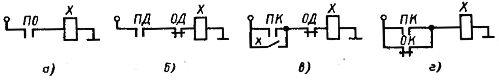
Rice. 3. Typical control schemes for executive and intermediate circuits
The first typical circuit (Fig. 3, a) has only one software control contact. If it is closed, then electric current flows through actuator X, and if it is open, no current flows. The PO contact has its own meaning and all other contacts must be used in pairs (start and stop).
The second typical circuit has two control contacts with continuous action: PD and OD (Fig. 3, b).
The third typical circuit consists of the start contact of the computer and the stop contact OD, in addition to the control contacts, this circuit should include a blocking contact x, through which the actuator X will continue to receive power after the start contact of the computer is opened (Fig. 3, c).
The fourth typical scheme is based on two short-term contacts: start a computer and stop OK, connected in parallel (Fig. 3, d).
The given four typical schemes allow (as if from cubes) to compose complex parallel-serial schemes for controlling contacts. So, for example, the lever control scheme under consideration (see Fig. 1) is based on the fourth typical scheme. It uses push buttons SB1 as short-term start contact and SQ limit switch as short-term stop contact.
When drawing up a control scheme using an intuitive method, it is necessary to correctly determine the type of control contact, that is, the duration of its action.
Consider an example of developing a control scheme using an intuitive method using typical schemes.
Let it be necessary to develop a semi-automatic device for controlling an inductor and a device for spraying an installation designed for heating a product with high-frequency currents and then cooling it with water jets. The product heating time in the inductor is 12 s and the cooling time is 8 h. The product is manually installed in the inductor.
First, we will analyze the operation of the semi-automatic device and determine all executive and intermediate elements. The worker manually installs the product into the inductor and presses the start button.At this point, the inductor turns on and the heating of the product begins. At the same time, the time relay should also turn on, taking into account the heating time (12 s).
This time relay (more precisely, its contacts) turns off the inductor and turns on the sprinkler, which supplies water for cooling. At the same time, a second relay must be turned on to count down the cooling time, that is, to turn off the sprayer. In this way, it is necessary to control four elements: an inductor, a spray device and two time relays.
The inductor is switched on and off via a contactor, which is why it is necessary to control the latter. The sprayer is controlled by a solenoid valve.
Let's designate the coil (coil) of the contactor KM1, the coil of the solenoid valve KM2 and the coils of the time relay KT1 and K.T2, respectively. Thus, we have two actuators: KM1 and KM2 and two intermediate elements: KT1 and KT2.
From the analysis carried out, it follows that the heating should start first, that is, the coil KM1 will be excited. The SB trigger button (short action) is used as a start contact. Thus, either the third or fourth typical scheme is applicable.
Let the inductor be disconnected from the contacts of the time relay KT1.1, which in this case are long-acting contacts. Therefore, we choose the third typical scheme. Simultaneously with the winding of the magnetic starter KM1, it is necessary to turn on the time relay KT1, which is very easy to do by connecting them in parallel.
Consider the operation of the resulting circuit (Fig. 4, a).
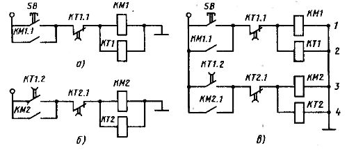
Rice. 4.Control circuits: a — inductor and relay for heating time, b — sprinkler device and relay cooling time, c — installation as a whole
When you press the start button SB, the coil of the contactor KM1 is energized, that is, the heating of the product begins. At the same time, the coil of the time relay KT1 is energized and starts counting down the heating time. With the help of the blocking contact KM1.1, the voltage of the coil KM1 will be maintained even after releasing the trigger button SB, i.e. after opening its contacts.
After the heating time has expired, the time relay KT1 will work, its contact KT1.1 will open. This will cause the KM1 coil to turn off (heating of the product will end). The sprayer should now be turned on. It can be turned on by the time relay KT1 by closing the contact. When the sprayer is turned on, the time relay KT1 is turned off. Therefore, the closing contact KT1.1 will be a short-term contact. Therefore, we will again use the third typical scheme.
Simultaneously with the sprayer, it is necessary to turn on the time relay KT2, which counts down the cooling time. For this purpose, we will use the applied technique and connect the coil of the time relay KT2 in parallel with the coil KM2. Thus we get the second control scheme (Fig. 4, b). Combining the two circuits (Fig. 4, a and b), we get a general control scheme (Fig. 4, c).
Let us now consider the operation of the circuit as a whole (Fig. 4, c). When you press the SB start button, the coils of the contactor KM1 and the time relay KT1 are energized and the product begins to heat up.After 12 s, the time relay KT1 will operate and its contacts in circuit 1 will open and in circuit 2 will close. The product will begin to cool. Simultaneously with the coil KM2 of the solenoid valve, the time relay K will be energized T2, counting down the cooling time. When the contact KT2.1 (circuit 3) opens, the valve KM2 and the time relay KT2 are turned off, and the circuit returns to its original position .
The resulting inductor and sprinkler control scheme was developed using an intuitive method. However, there is no evidence that this scheme will be correct and optimal. The question of the operability of the circuit can be resolved only after its production and careful experimental verification. This is precisely the biggest drawback of the intuitive method. The noted shortcoming is absent in the analytical method. The analytical method for developing control schemes will be discussed in the next article.