The three most popular asynchronous motor control schemes
All electrical diagrams of machines, installations and machines contain a certain set of typical blocks and nodes, which are combined with each other in a certain way. In relay-contactor circuits, the main elements of motor control are electromagnetic starters and relays.
It is most often used as a drive in metal cutting machines and installations three-phase squirrel-cage induction motors… These engines are easy to design, maintain and repair. They meet most requirements for electric drive of metal cutting machines. The main disadvantages of asynchronous squirrel-cage motors are large inrush currents (5-7 times higher than nominal) and the inability to smoothly change the speed of rotation of the motors by simple methods.
With the appearance and active implementation of electric circuits frequency converters such motors began to actively displace other types of motors (asynchronous with a wound rotor and DC motors) from electric drives, where it was necessary to limit the starting currents and smoothly adjust the rotation speed during operation.
One of the advantages of using squirrel-cage induction motors is the ease of connecting them to the grid. It is enough to apply three-phase voltage to the stator of the motor and the motor starts immediately. In the simplest version, a three-phase switch or a package switch can be used for inclusion. But these devices, with their simplicity and reliability, are manual control devices.
In the schemes of machines and installations, it is often necessary to predict the operation of one or another engine in an automatic cycle, to ensure the sequence of switching on several engines, to automatically change the direction of rotation of the engine rotor (reverse), etc. n.
It is impossible to provide all these functions with manual control devices, although in a number of old metal cutting machines the same reverse and switching of the number of pole pairs to change the speed of the motor rotor is very often carried out using packet switches. Switches and packet switches in circuits are often used as input devices that supply voltage to the machine circuit. The same engine control operations are performed electromagnetic starters.
Starting the engine with an electromagnetic starter provides, in addition to all the conveniences during driving, zero protection. What this is will be described below.
Three electrical circuits are most often used in machines, installations and machines:
-
control circuit of a non-reversible motor using one electromagnetic starter and two buttons "start" and "stop",
-
reversible motor control circuit using two starters (or one reversible starter) and three buttons.
-
a reversible motor control circuit using two starters (or one reversing starter) and three buttons, two of which use paired contacts.
Let's analyze the principle of operation of all these schemes.
1. The motor control scheme using a magnetic starter
The diagram is shown in the figure.
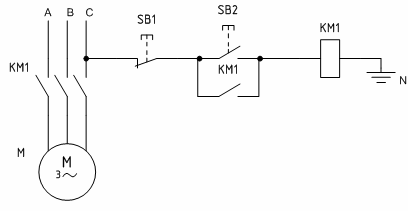
When you click on buttonSB2 "Start" of the starter coil comes under a voltage of 220 V, because it turns out that it is turned on between phase C and zero (H)... The moving part of the starter is attracted to the stationary one, simultaneously closing its contacts. The power contacts of the power supply starter voltage to the engine and the lock is closed in parallel with the «Start» button. Therefore, when the button is released, the starter coil does not lose power, because the current in this case flows through the blocking contact.
If the blocking contact would not be connected in parallel with the button (for some reason it is absent), then when the «Start» button is released, the coil loses power and the starter power contacts open in the electrical circuit, after which it is turned off. This mode of operation is called «jogging». It is used in some installations, for example in crane beam schemes.
Stopping a running engine after starting in a circuit with a blocking contact is carried out using the SB1 "Stop" button. At the same time, the button creates a circuit break, the magnetic starter loses power and with its power contacts disconnects the engine from the mains.
In the event of a voltage interruption for any reason, the magnetic starter also shuts down, because this is the same as pressing the Stop button and creating a circuit break.The engine stops and its restart in the presence of voltage is possible only by pressing the SB2 "Start" button. Thus, the magnetic starter provides the so-called "zero protection". If it was missing in the circuit and the motor was controlled by a switch or a pack switch, then when the voltage returned, the motor would start automatically, posing a serious hazard to service personnel. Check more details here — undervoltage protection.
An animation of the processes taking place in the diagram is shown below.
2. Control circuit of a reversible motor using two magnetic starters
The scheme works similarly to the previous one. Changing the direction of rotation (reverse) the rotor of the motor changes when the order of rotation of the phase of its stator changes. When the KM1 starter is turned on, the phases come to the motor — A, B, C, and when the KM2 starter is turned on, the phase order changes to C, B, A.
The scheme is shown in fig. 2.
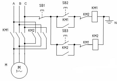
Turning on the motor for rotation in one direction is carried out by the button SB2and electromagnetic starter KM1... If it is necessary to change the direction of rotation, press the button SB1 «Stop», the motor will stop, and then when you press the button SB3 the motor starts rotating in opposite direction. In this scheme, to change the direction of rotation of the rotor, it is necessary to press the «Stop» button between them.
In addition, in the circuit it is mandatory to use normally closed (NC) contacts in the circuits of each of the starters to ensure protection against the simultaneous pressing of two «Start» buttons SB2 — SB3, which will lead to a short circuit in the supply circuits of the engine.Additional contacts in the starter circuits do not allow the starters to turn on at the same time, because each of the starters, when the two "Start" buttons are pressed, turn on a second earlier and open its contact in the circuit of the other starter.
The need to create such blocking requires the use of starters with a large number of contacts or starters with contact attachments, which increases the cost and complexity of the electrical circuit.
Below is an animation of the processes taking place in a circuit with two starters.

3. Reversible motor control circuit using two magnetic starters and three buttons (two of which have mechanical linkage contacts)
The diagram is shown in the figure.
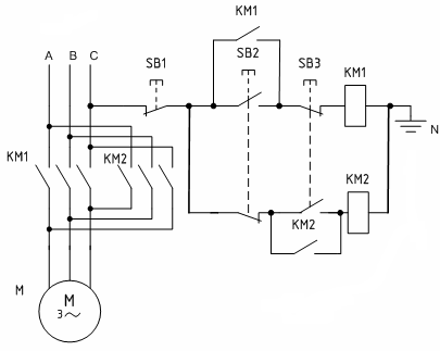
The difference between this circuit and the previous one is that in the circuit of each starter, in addition to the common button SB1 «Stop» includes 2 contacts of buttons SB2 and SB3, and in the circuit KM1 the button SB2 has a normally open contact (close) and SB3 - normally closed (NC) contact, in the circuit KM3 — button SB2 has a normally closed contact (normally closed) and SB3 — normally open. When each of the buttons is pressed, the circuit of one starter is closed and the circuit of the other is opened at the same time.
This use of buttons allows you to refuse the use of additional contacts for protection against the simultaneous activation of two starters (this mode is not possible with this scheme) and gives the opportunity to go back without pressing the Stop button, which is very convenient. The Stop button is used to completely stop the engine.
The diagrams given in the article are simplified. They lack protective devices (circuit breakers, thermal relays), alarm elements.Such circuits are also often supplemented by various contacts for relays, switches, switches and sensors. It is also possible to supply the winding of the electromagnetic starter with a voltage of 380 V. In this case, it is connected from any two phases, for example, from A and B... It is possible to use a step-down transformer to reduce the voltage in the control circuit. In this case, electromagnetic starters with coils for voltages of 110, 48, 36 or 24 V are used.