Protection of rural electrical networks voltage 0.38 kV
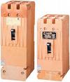 Transformer bushings, as well as 0.38 kV overhead lines extending from 10 / 0.4 kV (20-35 / 0.4 kV) transformer substations, are protected against short circuits. circuit breakers such as AP-50, A3124, A3134, A3144, A3700 or blocking «fuse» type BPV-31-34 with fuses type PR2.
Protection using automatic switches can be carried out with built-in thermal electromagnetic releases and releases in the neutral wire, as well as with switches that, in addition to electromagnetic current release, have an independent release. Single-phase short-circuit protection is provided by the RE-571T current relay in the neutral wire, which acts on the shunt release of the machine.
In order to coordinate the action of protections made by automatic devices and fuses, combined protection characteristics of response time are used.
Operational experience shows that the fuse works selectively with the automatic device under the condition Ic ³ 1.2 • In.r.
To protect the power transformers on the 10 kV side in rural power networks, computer fuses are often used. The current of the condensed connection is determined by the expression Iv = (1.5¸2) • Inom. tr.
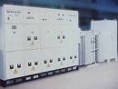
Protective device for overhead lines 0.38 kV, type ZTI-0.4
 To increase the sensitivity of short circuit protection. Currently, the Pyatigorsk Experimental Plant "Soyuzenergoavtomatika" is serially producing protective ZTI-0.4 for 0.4 kV distribution networks. The device is intended for installation in 10 / 0.4 kV KTP with a power of 63,100 and 160 kVA instead of ZT-0.4 protection.
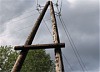
Compared to the ZT-0.4 device, the ZTI-0.4 protection has higher current accuracy and phase-to-phase and single-phase to neutral short-circuit current accuracy, operates in the event of an earth fault, which naturally makes it possible to increase the level of reliability and Electrical safety 0.38 kV lines. According to VNIIE data, on average, one 0.38 kV overhead line has two failures per year.
 The principle of implementation of protection ZTI-0.4 against earth faults is based on monitoring the magnitude of the ground current or switching current and its component in the neutral wire and comparing these values through the proportionality factor, since it was found that when switching a single-phase load and earth the ratio of the total switching or earth fault current to its component in the neutral wire is different in load switching and in the case of an earth fault.
The earth fault current I3 or the switching current In, during operation of 0.38 kV lines under load, differs as the difference between two values of the unbalance current of three phases before and after the occurrence of an earth fault (or switching of a single-phase load ), that is, as an increase in the phase current of the unbalance of three phases.
Ic (In) = Iph1 — Iph2 = DIph
where Iph1 = IA + IB + IC is the unbalance current of the three phases before grounding (ZNZ);
If2 = IA + IB + IC + Ic — unbalance current of three phases after h. n. z. (single-phase load switching).
The component of these currents in the neutral conductor in s. n. z. (single-phase load switching):
Iоs (Iоn) = Iо1 — Iо2 = DIо
where Io1 is the neutral wire current to s. n. z. (single-phase load switching);
Iо2 — zero current conductor after s. n. z. (single-phase load switching).
Rice. a — block diagram of protection ZTI -0.4: T — voltage transformer; TA — current transformer; b — protection connection diagram ZTI -0.4: QF — breaker; AK — device ZTI — 0.4; HP — QF circuit breaker shunt release coil terminals
The principle of protection against z. n. z. can be understood from the following expression: DIph — mn DI0> Upn while the output of the circuit performs the necessary commutation when DIf — mn DI0 <Un. where DIph is the increase in unbalance current of the three phases; DI0 — current increase in the neutral wire; Up is a constant value; mn — proportionality factor.
The output of the circuit does not change its state.The main advantage of the ZTI-0.4 device is its failure to respond to leakage currents in normal mode when switching a single-phase load, which significantly increases its sensitivity.
The ZTI-0.4 device is designed to protect three-phase four-wire 0.38 kV overhead lines with dead earthed neutral and multiple earthing of the neutral wire from single phase to neutral wire and phase-to-phase faults and from phase-to-earth faults. The ZTI-0.4 protection is designed for one line with a voltage of 0.38 kV and an operating current of up to 160 A.
The ZTI-0.4 device has four current inputs for connection to the line, through which three phase and neutral conductors pass. The ZTI-0.4 has shunt automatic release connection clamps with a rated operating voltage of 110 V DC, with a rated current of 2A.
Remote relay protection against single-phase short circuit in networks 0.38 kV
 In most cases, with the help of circuit breakers or starters (contacts), it is not possible to provide the necessary speed for three tripping of single-phase short circuits. in electrical installations with a voltage of up to 1000 V with a solidly grounded neutral, it is recommended to use an external relay protection (RP). Operational experience has shown high reliability of relay protection from single-phase short circuits. with starter tripping action that responds to zero-sequence currents. The overcurrent relay is connected to a zero-sequence current transformer (TTNP) that spans the power cable.
Remote relay protection must be operated with a low voltage release or shunt. If the circuit breaker does not have a release, a starter trip circuit must be used.On output lines protected by fuses, if necessary, protective protection is installed in the fuse circuit, a starter is installed.
Single-phase protection circuit. using a zero voltage release is shown in Fig. uncovered.
Single-phase short-circuit protection circuit: KK1-electrothermal relay; TA — current transformer; KM1— magnetic switch; QF1, QF2 — automatic switches; FU1 — fuse.
With a single-phase short circuit. relay KA1 is activated type RT-40, which through its contact KA11 opens the supply circuit of the relay K.L1 of the RPU2 type, the relay KL1 through its contact opens the supply circuit of the zero voltage release. This splitter trips circuit breaker QF1 when the voltage at its coil terminals drops to 0.3 Un, regardless of the operation of the single-phase short-circuit protection. The above diagram is recommended to be used on outgoing power lines for which external short-circuit tripping is permissible.
Special residual current protection against single-phase short circuit. to the ground in the network 0.38 kV
 Power networks of 0.38 kV operate with a solidly grounded neutral of transformers with a connection scheme D / g and g / g winding. At closed transformer substations (ZTP) 10 / 0.4 kV, transformers with a capacity of more than 400 kVA with a D / g winding connection scheme are used.
With a single-phase short circuit. for side earthing at a short-circuit current value of 0.4 kV turns out to be about three times higher than with the same efficiency. behind the same transformer but with the g / g coil connection diagram. This provides a higher sensitivity of both the special residual current protection 0.38 kV and overcurrent protection 10 kV transformers with D / g winding connection diagram.
Special zero-sequence current protection can be carried out, for example, by including a protective current transformer in the neutral wire (neutral), to the secondary winding, to which a maximum current relay of the RT-40 or RT-85 type is connected.
With a single-phase short circuit. on the side of 0.4 kV short-circuit current passes through the damaged phase and neutral of the transformer, is transformed through a current transformer into a current relay of the RT-40 (RT-85) type and triggers a special zero-sequence current protection to turn off 10 kV circuit breaker and 0.4 kV circuit breaker.
This protection is highly sensitive to any single phase short circuit. behind a transformer with metal and transient resistance at the point of failure. Scheme of special current protection of zero sequence of single-phase short circuits. to the ground in the 0.38 kV network is shown in the figure.
Scheme of special current protection of zero sequence of single-phase short circuits. to the ground in the 0.38 kV network: 1TA, 2TA — current transformers; AK — maximum current protection; KA-relay for maximum current of type RT-40 (RT-85) with special current protection; OF1, QF2 — breaker; I-current of a single-phase short circuit. k1-point of a single-phase short circuit.
It is recommended to install this protection on 10 / 0.4 kV transformers protected by fuses on the 10 kV side. However, it only operates when the breaker is opened on the 0.4 kV side.