Magnetic amplifiers in metal cutting machines
The magnetic amplifier switches the electrical circuit by changing its inductive electrical resistance within wide limits, the value of which depends on the degree of saturation of the magnetic circuit.
Magnetic amplifiers are widely used in electric drives of metal-cutting metal-cutting machines due to their reliability and long service life (it is considered one of the most reliable elements of automation systems), the absence of moving parts, the possibility of performing magnetic amplifiers with a power of fractions of watts to hundreds of kilowatts, high strength and durability in terms of vibration and shock load. Moreover, thanks to magnetic amplifiers, it is possible to easily sum the signals. They have high profit. In magnetic amplifiers, there is no electrical connection between the input and output circuits.
The principle of operation of the magnetic amplifier is based on the use of the nonlinearity of the magnetization curve of a ferromagnetic material.When DC magnetized, the amplifier core saturates and the inductance of the amplifier's operating AC coils decreases. The operating windings are usually connected in series with the load. Therefore, the voltage that is applied to the operating windings of the amplifier at the moment of saturation before the core saturates is applied to the load.
The load current is controlled by varying the current in the bias coil of the magnetic amplifier. The bias coil is used to create the initial bias necessary to change the current in the load in different ways depending on the sign of the polarity of the control signal, as well as to select a point on the straight-line section of the characteristic. The feedback coil is designed to obtain the required shape of the output characteristics.
Structurally, the magnetic amplifier is a core made of sheet ferromagnetic material on which AC and DC coils are wound. To eliminate interference, e.g. etc. c. AC circuits of DC coils AC coils are wound separately on the core and DC coils cover both cores.
Scheme of the simplest magnetic amplifier
A magnetic amplifier may have several control coils. In this case, in the operating mode, the current in the load will be determined by the total control current. That is, it can be used as an adder of unrelated electrical signals (permanent signals are summed).
Magnetic amplifiers can be both inverting and inverting. In irreversible magnetic amplifiers, a change in the polarity of the control signal does not cause a change in the phase and sign of the load current.
The cores of magnetic amplifiers are made of both transformer steel and permaloid, and transformer steel is used when the power of the magnetic amplifier is greater than 1 W. The magnitude of the magnetic induction in the steel core of the transformer reaches 0.8 — 1 .0 T. The amplification factor of such magnetic amplifiers varies from 10 to 1000.
Permalloy is used in magnetic amplifiers whose power is less than 1 V. Rectangular character hysteresis loops for permaloy allows to get a profit from 1000 to 10,000 and more.
The core of the magnetic amplifier is loaded from separate plates, such as the cores of chokes or transformers. Magnetic amplifiers based on toroidal cores have gained wide distribution, which, despite the technological difficulties in their production, have a number of advantages, the first of which is the absence of air gaps , which improves the characteristics of the magnetic amplifier.
The following schemes of magnetic amplifiers are widespread: single and push, reversible and irreversible, single-phase and multi-phase.
In metal-cutting (and not only metal-cutting) machines, you can find a very wide variety of designs of magnetic amplifiers: single-phase UM-1P series, three-phase UM-ZP series assembled on six U-shaped cores made of E310 steel, single-phase TUM series on toroidal core, block magnetic amplifiers of the BD series, containing, in addition to magnetic amplifiers, step-down transformers, diodes and resistors assembled on one panel. Electric drive systems can be built on any amplifiers in this series.
Winding circuit of the UM-1P magnetic amplifier
In addition, complete drives with magnetic amplifiers and DC motors are often used on various metal cutting machines, for example, a very common drive with magnetic amplifiers PMU. But we will certainly talk about it next time. In addition, in the next post we will focus on the methods of tuning magnetic amplifiers and touch on a number of other issues that are of interest to anyone who constantly encounters or will encounter in the future when working with magnetic amplifiers.
Full electric drives with magnetic amplifiers
Despite the fact that static converters (thyristors, power transistors, IGBT modules), in our industrial plants it is still very common to see electric motors and DC generators working in combination with magnetic amplifiers.
Magnetic amplifiers were most widely used in industrial equipment in the 1950s. In general, in the era of semiconductor technology, there is the following trend - asynchronous and synchronous (for high power) drive is used in unregulated electric drive and DC device with electric or static (thyrotron or mercury rectifier, magnetic amplifier) for controlled.
Currently, most often in domestic enterprises in the schemes of electrical equipment of metal-cutting machines, machines and installations, it is possible to find complete direct current electric drives with magnetic amplifiers of the PMU series.
PMU — drive with magnetic amplifiers and selenium rectifiers. The motor speed adjustment range is 10: 1. The adjustment is made by changing the armature voltage from the rated motor speed.Automatic control system with electronic feedback. d s. engine, without tachogenerator and intermediate amplifier. Drive power from 0.1 to 2 kW. The drive is designed for a rectified bridge output voltage of 340 to 380 V. To obtain sufficiently stiff drive characteristics, negative current and voltage feedbacks are introduced into the circuit.
Each PMU series drive is a set consisting of a power supply unit, rectifiers, magnetic amplifiers, a DC motor and a speed controller.
The drive works as follows. The voltage applied to the motor automatically follows the signal depending on the change in its speed. As the engine speed decreases, the voltage increases and vice versa: the voltage maintains the speed value with a given accuracy, regardless of the load change and other disturbing factors.
The influence of various disturbing factors on the speed of rotation compensates for the reactivity of the working coil of the magnetic amplifier: as the load increases, the current in the armature increases, which leads to a decrease in the resistance of the working coil of the magnetic amplifier. Due to a decrease in the resistance of the working coil, the voltage in the motor armature increases, the current in the windings increases, which further reduces the impedance of the windings of the working amplifier. As a result of the general decrease in the resistance of the working coil, the voltage in the motor armature increases , which compensates for the reduction in engine speed. The required motor speed is set using set point P and resistors R1 — R4.
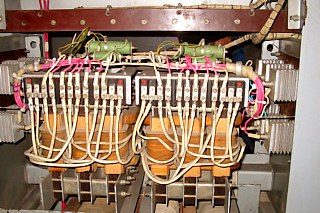
The PMU-M is similar to the PMU series, but the magnetic amplifiers are assembled on U-shaped cores. Drive power PMU-M from 0.1 to 7 kW.
PMU-M device
PMU-M series drives use an automatic speed control system with motor armature voltage and current feedback. The magnetic amplifier has two sets of control coils. A control current flows through one of them, which is the algebraic sum of the setpoint current and the feedback currents, and the other (bias coil) serves to select the operating point of the straight section of the characteristic of the magnetic amplifier.
To protect against unacceptably high armature current values, PMU-M drives sizes 8 to 11 are equipped with a current limiter. When the armature current exceeds the permissible values, the overcurrent relay is activated, its open contact opens and interrupts the supply circuit of the control coil. As the bias coil remains closed, the magnetic amplifier is de-energized and the armature current is reduced. The operation of the PMU-M drive circuit is similar to the operation of the PMU drive circuit.
PMU -P — drives with increased accuracy and extended control range 100: 1. Automatic control system with feedback for the rotation frequency, which is carried out using a tachogenerator and an intermediate semiconductor amplifier. Motor speed is adjusted by varying the armature voltage.
By the way, magnetic amplifiers can also be used to regulate the voltage at the terminals of the asynchronous motor, as well as contactless starters.
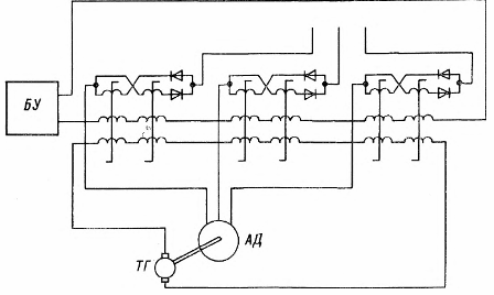
Magnetic amplifier-induction motor system