Fault finding in relay-contactor circuits. Part 2
Check out the start here: Fault finding in relay-contactor circuits. Part 1
Example 7. Defect criteria.
Let the working state of the coil relay characterized by only one parameter — resistance R = 2200 ± 150 Ohm.
In this case, during a planned preventive check of the resistance of the relay based on the deviation of the actual resistance outside the tolerance, the presence of defects reported in examples 1,2.
At the same time, the relay coil with the defect indicated in example 3 will be classified as working.
The presence of a defect in a product operating as intended is recognized by the activation of protective and alarm devices or by the occurrence of unacceptable deviations of the observed parameters.
Example 8. Determining the presence of a defect.
The consumer of electricity receives energy through the contacts of the circuit breaker (machine) equipped with a dependent release having the current-time characteristic shown in fig. 3.
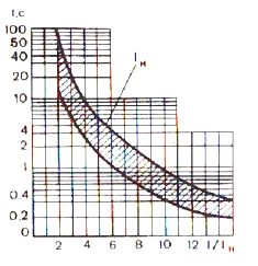 Rice. 3 Circuit breaker time current characteristic
If the machine does not interrupt the user's power supply, then it is considered that there are no defects in the power supply system of the electrical installation. Otherwise, they consider the defect to exist and continue to establish the reason that caused the issue to be released.
Naturally, the serviceability of the release and the machine itself must be periodically checked.
Finally, the presence of defects in the product is indicated by the occurrence of a specific accident (accident). Unlike those discussed earlier, such a situation is not the norm, and in the part that does not affect the process of searching for a defect of interest to us, it should be considered as an emergency.
Summarizing what has been said, we note that in technical diagnostics, regardless of how they learned about the fact of the presence of a defect, it is customary to say that the search for a defect begins after it is shown.
According to the above definition, any defect is a deviation from any norm. As long as there is no such deviation, that is, the defect has not appeared, then there is no defect itself.
Therefore, the existing opinion that defects should be detected and removed in advance so that they do not manifest erroneously, as this contradicts the basic concepts of technical diagnostics and the theory of reliability.
Applying certain checks, it is not always possible to establish the fact of the presence of a defect in the product (see example 3), therefore, in connection with the rules, methods and means of control, all defects are divided into explicit and hidden.
Obvious defects can be detected by the methods and means of control provided for in the product documentation.
For example, suppose that the relay documentation only has one way to check the health of the coil — via the coil resistance. In this case, the defects described in examples 1, 2, according to the accepted classification, will be obvious. The defect indicated in example 3 for this control method refers to hidden.
Such a classification does not give grounds for claiming that hidden defects cannot be detected at all. It's just that individual defects are hidden from any particular control method and a different method must be used to identify them.
Example 9. Revealing a hidden defect.
Let the working state of the coil be characterized by the following two parameters: resistance of the coil R1 = 2200 ± 150 Ohm; shocked I = 0.05 + 0.002 A.
Therefore, the health of the coil is monitored by measuring resistance and current.
With this monitoring method, the defect (example 3) ceases to be hidden, since the actual value of the current Az = 0.053 A exceeds the permissible 0.052 A.
All defects in the winding of the relay, which reduce its resistance by less than 150 Ohm or lead to an increase in the current consumed by it by no more than 0.02 A, and for this method of monitoring the operation should be classified as hidden .
The appearance of a defect leads to specific changes in the product (breakage of wires, incorrect connection of elements to each other, short circuit of current-carrying parts that are not provided by the circuit, breakdown of parts), which are called the nature of the defect.
On this basis, defects are subdivided into electrical and non-electrical.
Electrical defects include violations of contact connections, short circuits, open circuits, errors in connecting elements to each other, etc.
Of all the possible non-electrical defects, let's pay attention only to some mechanical defects, such as: malfunctions in the fasteners of the elements, the transmission systems from executive motors (servomotors) to the controls, in the moving parts of relays and contactors, etc.
So far, examples have been given with one defect in the product. In the general case, however, a product may have more than one defect, and the product is then said to have multiple defects.
Nevertheless, in the work of technical diagnostics, the process of searching for defects is described under the assumption that there is only one defect in the product at a time.
This convention is caused both by the low probability of the simultaneous appearance of two, and even more three or four defects, and by the fact that one defect always manifests itself most clearly, and the other (or others) on its background remains undetected.
The search for multiple defects begins when, after the removal of the first one found during the control of the product's health and operability, the presence of another defect is detected.
Sometimes it is believed that there are cases where multiple defects compensate each other. However, this does not correspond to the true state of affairs, which also follows from the definition of defect introduced above. In fact, in the presence of multiple defects, it is possible, in addition to a bright manifestation of one of them, to distort the external manifestations due to the combined action of several defects.
Example 10. Multiple Defects.
 The basis of the circuit for the protection of an electrical installation against a short circuit is the relay part, which reacts to one of its parameters and sends a signal to the disconnecting electromagnet of the circuit breaker, through which the electrical installation receives power.
Let there be a defect in the relay part that causes it to operate both in the event of a short circuit in the protected area and outside it. Let there be a second defect at the same time, causing the trip solenoid to fail.
Due to the fact that, due to technological reasons, the power supply from the protected installation is not removed, the defect of the disconnecting electromagnet is not manifested in any way.
Due to the presence of such a defect, a defect in the relay part does not appear, although it is triggered by a short circuit outside the protection zone.
Thus, outwardly, the protective circuit and circuit breaker appear to be in good working order.
If it is necessary to avoid an emergency situation that occurred in the event of a short circuit in the area protected by the relay part, then you can learn about the presence of a defect by performing periodic joint checks of the protection and actuation of the circuit breaker without interrupting the control circuits.
But in order to establish the fact of the simultaneous existence of two specific defects, such an inspection is no longer sufficient, and it is necessary to develop special criteria and test methods that make it possible to draw a reasonable conclusion that the external manifestations characteristic of a given inspection is the result of the coexistence of only these two defects and no others.
Such a picture will be described not only in the case of failure of an electromagnet, but also in the event of a break in any wire connecting the electromagnet to the relay part, as well as in the event of a violation of any of the contact connections in an electromagnetic circuit and other similar defects.
The failure of the relay part in the event of a short circuit in the protection zone can also be caused by the presence of a short circuit in the secondary circuit of the current transformer, which generates a signal arriving at the input of the relay part.
Examples that are similar in the manifestation of defects can be significantly multiplied. Therefore, it turns out to be not only convenient, but also more correct to construct the process of searching for a defect (after establishing the fact of its existence), assuming that there is only one defect in the product.
As can be seen from example 10, the same manifestation of different defects does not allow in each specific case to indicate which specific defects exist in the product. In our case, you can list only a group of defects that have the same external manifestations (or, in other words, have the same image).
Example 11. External manifestations of multiple defects.
Let's check the serviceability of the sensitive part of the relay by measuring the current consumed by the coil and the result of the measurement I> Iadd. Thus, the check shows that there is a defect in the relay. The increase in current in the coil is caused not only by electrical (for example, a short circuit), but also by mechanical (in the moving part of the relay) defects.
A detected increase in current above the permissible limit may be the result of the presence of both an electrical and a mechanical defect, and both at the same time.
This example illustrates the fact that the manifestation of multiple defects may not differ at all from the manifestations of single ones, and only from the results of measuring the current in the coil it is impossible to say for what reason it has increased.
To identify multiple defects, they do it differently. First, they look for the defect that manifests itself most clearly, and then, having eliminated its cause, they check the product's operation again.
If such an inspection confirms the presence of deviations from the requirements established for the product, then they begin to look for the defect that corresponds to the established deviations.
With respect to the material of Example 11, this means that at I> Iadm. you must first make sure that there is no short circuit (for example, by measuring the resistance of the coil), and then, if the resistance is normal, check the mechanical part of the relay.
However, you can proceed in a different way by first checking the mechanical part of the relay and then its coil.
Thus, it turns out that even when looking for such an elementary defect, it is not easy to choose one or another sequence of checks, as well as technological transitions with the help of which these checks are carried out.
Therefore, in technical diagnostics, the defect is determined on the basis of some method that establishes the rules for the application of certain principles, the use of technological means and the choice of technological transitions for carrying out checks.
Regardless of the chosen method of defect identification, it is necessary first to study the product as an object for defect search, to identify possible defects in it and their signs, to develop product models that describe the working and defective states, to determine the sequence and composition of checks and select technological transitions for their implementation.
To successfully search for a defect, it is not necessary to know everything about the elements that make up a real object, the connections between them, as well as about the various "subtleties" and "peculiarities" of its operation. In addition, excessive information often not only does not speed up the search, but, on the contrary, complicates it. In particular, due to the fact that not every defective element can be replaced with a correct one.
Therefore, when determining the depth of search, they are primarily guided by the plug-in level (board, node, module, etc.) and much less often at the element level.
Therefore, when a defect is detected, the real object is replaced by a model.
It should be borne in mind that the same product can be represented by different models, depending on which of its properties are of interest at the moment.
Technological transition is a complete part of a technological operation, characterized by the immutability of the technological equipment used. In our case, the operation is a search for a defect and one of the technological transitions — the measurement was considered in examples 1, 2, 3.
The most common models are different types of diagrams (structural, functional, principle, connections, connections, equivalent, etc.), which differ in that they represent the same product from different sides and with different degrees of detail.
Therefore, first, product diagrams are used as models. And only in those cases when the circuit is not enough to detect a defect, there are special diagnostic models designed to determine defects.
You can use either one model or several, replacing them in the process of finding a defect.
Of all those used, the most common diagnostic model is in the form of a list of defects (Table 1).
Table 1. Diagnostic model in the form of a list of defects for the light and sound alarm system
External manifestations Cause Corrective actions All indicators and display are off Absent feeding (operational current). Defective MPVV. Defective MCP Check Availability of supply voltage Replace MPVV. Replace ICP Display after pressing buttons not included in flow 10 with Reduced contrast display defective ICP Defective remote control Adjust contrast display Replace ICP Replace unit After feeding Power indicator blinks or operation indicator is off. On the display in the menu «Test» the inscriptions: «Defective» «MPC UST» Destroyed or not entered set values and provisions of the program keys Present new set values and program keys. If the defect persists -replace ICP Blinking or canceled indicator «Operation», indicator «Call» is cancelled. On the display v menu «Test» the inscriptions «Defective», «MAC» 1. Analogue input signal shakes the maximum permissible meaning 2. Defective MAC Defective MPVV (power supply ± 15 V) 1.Check the analog inputs and On menu «Network settings» 2. Replace MAC 3. Replace MPVV
This model is compiled on the assumption that the search for a defect is carried out before the element - relay, lamp, socket, wire.
The process of searching for defects using such a model is extremely simple. By comparing the manifestations of a real defect with those given in one column of such a list, the cause of the defect and a method of remedying it are found in the other. I am.
For electrical machines, such a model is described in the classic book by RG Gemke.
The scope of this method of searching for defects is limited primarily by the fact that it is practically impossible to compile an exhaustive list of defects for a more or less complex product, i.e. it is impossible to build a diagnostic model that takes into account all possible defects.
Oleg Zakharov "Searching for defects in relay-contactor circuits"