Brake circuits for asynchronous motors
 After disconnection from the mains, the electric motor continues to move. In this case, kinetic energy is used to overcome all kinds of resistance to motion. Therefore, the speed of the electric motor after a period of time, during which all the kinetic energy will be used up, becomes equal to zero.
Such a stop of the electric motor in free-running inertia... Many electric motors, working continuously or with significant loads, are stopped by free-running.
In those cases where the free-flow time is significant and affects the operation of the electric motor (operation with frequent starts), an artificial method of converting the kinetic energy stored in the moving system, the so-called stopping.
All methods of stopping electric motors can be divided into two main types: mechanical and electrical.
 During mechanical braking, kinetic energy is converted into heat energy, due to which the friction and adjacent parts of the mechanical brake heat up.
In electric braking, kinetic energy is converted into electrical energy and, depending on the method of braking the motor, is either released to the grid or converted into thermal energy, which is used to heat the motor windings and rheostats.
Such braking schemes are considered the most perfect, in which the mechanical stresses in the elements of the electric motor are negligible.
Dynamic braking circuits for asynchronous motors
For torque control during dynamic braking phase rotor induction motor according to the program with time setting, the nodes of our circuits are used fig. 1, of which the scheme stris. 1, and in the presence of a DC network, and the diagram in fig. 1, b — in its absence.
The braking resistors in the rotor are starting resistors R1, the activation of which in the dynamic braking mode is carried out by turning off the acceleration contactors shown in the nodes of the circuits in question, conditionally in the form of one contactor KM3, the shutdown command is given by the blocking contact of Line contactor KM1.
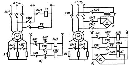
Rice. 1 Control circuits for dynamic braking of wound-rotor induction motors with timing adjustment in the presence and absence of a permanent network
The equivalent value of the DC current in the stator winding during braking is provided in the circuit of Fig. 1, and an additional resistor R2, and in the circuit of fig. 1.b through an appropriate selection of the transformation coefficient of the transformer T.
The KM2 brake contactor can be selected for either direct current or alternating current, depending on the required number of starts per hour and the use of starting equipment.
The given fig.1 control circuits can be used to control the dynamic braking mode squirrel cage rotor asynchronous motor… For this, a transformer and rectifier circuit, shown in the diagram, is usually used. 1, b.
Braking circuits by opposing asynchronous motors
In braking torque control by opposing a speed-regulated squirrel-rotor induction motor, the circuit diagram shown in Fig. 2.
As an anti-switching relay it is used speed control relay SR mounted engine. The relay is set to a voltage drop corresponding to a speed close to zero and equal to (0.1 — 0.2) ωmouth
The chain is used to stop the motor with opposite braking in reversible (Fig. 2, a) and in irreversible (Fig. 2, b) circuits. The SR command is used to turn off contactors KM2 or KMZ and KM4, which disconnect the stator winding from the mains voltage at motor speed close to zero. In reverse SR commands are not used.
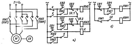
Rice. 2 nodes of the braking control circuit by opposing a cranked open-rotor induction motor with braking speed control in reversible and non-reversible circuits
The control block for a single-stage counter-switched stop mode wound-rotor induction motor consisting of R1 and R2 is shown in Fig. 3. Anti-switching control relay KV, which is used, for example, voltage relay DC type REV301, which is connected to two phases of the rotor through a rectifier V. The relay adjusts to the voltage drop.
An additional resistor R3 is often used to set the KV relay.The circuit is mainly used in blood pressure reversal with the control circuit shown in fig. 3, a, but can also be used in braking in an irreversible control circuit shown in fig. 3, b.
When starting the engine, the switching anti-relay KV does not turn on, and the switching stage of the rotor resistor R1 is output immediately after the start control command is given.
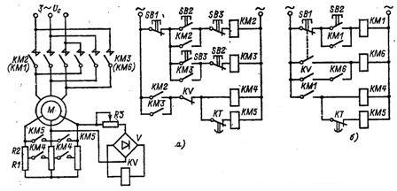
Rice. 3. Nodes of control circuits for braking by opposing wound-rotor induction motors with speed control during reverse and braking
In the reverse mode, after giving a command to reverse (Fig. 3, a) or stop (Fig. 3, b), the slip of the electric motor increases and the KV relay turns on.
The KV relay turns off the contactors KM4 and KM5 and thus introduces the impedance Rl + R2 into the motor rotor.
At the end of the braking process at an induction motor speed close to zero and approximately 10 — 20% of the set initial speed ωln = (0.1 — 0.2) ωset, the KV relay is turned off, giving a stage shutdown command to flow R1 using contactor KM4 and to reverse the electric motor in a reversible circuit or command to stop the electric motor in an irreversible circuit.
In the above schemes, a control controller and other devices can be used as a control device.
Mechanical braking schemes for induction motors
When stopping asynchronous motors, as well as to hold the movement or the lifting mechanism, for example in industrial crane installations, mechanical braking is applied in a stationary state with the engine off. It is provided by an electromagnetic shoe or other brakes with three-phase electromagnet alternating current which, when switched on, releases the brake. The brake solenoid YB turns on and off together with the engine (Fig. 4, a).
The voltage to the brake solenoid YB can be supplied from the brake contactor KM2, if it is necessary to turn off the brake not simultaneously with the engine, but with a certain time delay, for example, after the end of the electric brake (Fig. 4 , b)
Provides time delay time relay KT receives a command to start the time, usually when the contactor of the line KM1 is turned off (Fig. 4, c).
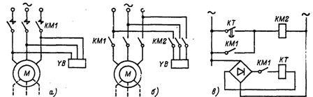
Rice. 4. Nodes of circuits that perform mechanical braking of asynchronous motors
In asynchronous electric drives, electromagnetic DC brakes are also used when controlling an electric motor from a DC network.
Capacitor braking circuits for asynchronous motors
Also used to stop AM with a squirrel cage rotor capacitor braking self-excited. It is provided by capacitors C1 — C3 connected to the stator winding. Capacitors are connected according to the star scheme (Fig. 5, a) or triangle (Fig. 5, b).
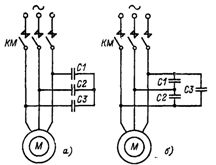
Rice. 5. Nodes of circuits that perform capacitor braking of asynchronous motors