Blockages in electrical circuits of metal cutting machines
 Interlocks in electric circuits ensure the correct order of operation of circuits, exclude false and emergency switching on of devices and increase the reliability of operation of electric drive circuits.
By prior arrangement, blocking in electric circuits of electric drives of metal-cutting machines are divided into technological and protective ones. According to the implementation of blocking, there are internal ones, performed between devices of the same circuit (electrical and mechanical), and external ones - between the circuits of different drives (electrical).
Locking an electrical product — a part of an electrical product (device) designed to prevent or limit the performance of operations by some parts of the product under certain conditions or positions of other parts of the product to prevent unacceptable conditions from occurring in it or to exclude access to its live parts (GOST 18311-80) ...
Technological interlocks are used to perform a given sequence of actions on an electrical circuit.They are internal and external. An example of internal technological blocking is a node of the chain shown in fig. 1, a, where the blocking open contact of the dynamic stop relay KT (KV) ensures in reverse the switching on of the contactors (magnetic starters) KM3 or KM4 only after the end of the dynamic braking process.
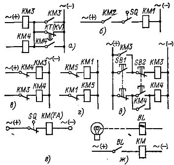
Rice. 1. Locking the electrical circuits
An example of external technological blocking in an electric circuit can be the permission or prohibition of operation of one electric drive when another electric drive is working or not working, one or more mechanisms connected by a common technological process.
In fig. 1, b shows a circuit diagram with two external interlocks that ensure that contactor KM1 is turned on only after contactor KM2 (another electric drive) is turned on and in a certain position of the mechanism (only when motion switch SQ).
Safety interlocks prevent false alarms in the circuit and protect motors, machines, and sometimes operators from improper operation. An example can be used in electrical circuits to block reversing contactors (magnetic starters) KMZ and KM4 (Fig. 1, c) or linear KM1 and brake KMZ contactors (Fig. 1, d), which exclude the simultaneous false inclusion of KM3 and contactors KM4 or KM1 and KM5.
These locks are internal. Usually, they are carried out using a mechanical connection (lever), which prohibits their simultaneous activation, and additional electrical methods using interrupting contacts KM3 and KM4 or KM1 and KM5 (Fig. 1, c, d) and two-element control buttons (Fig. 1, e). See also: Connection diagrams of a magnetic starter for controlling an asynchronous electric motor.
Protective interlocks in electrical circuits of electric drives of metal-cutting machines include movement interlocks (Fig. 1, e), limiting the movement of mechanisms and protecting them from breakage, and interlocks that protect the operator from his wrong actions, for example, in presses, where the details are installed manually, photoelectric protective blocking from the BL photosensor (fig. 1, g).