Motor control circuits as a function of road
 Directional automation or control in a path function is used to limit the movement of a mechanism or stop it at any intermediate or end point of the path.
The main options for controlled duty cycles elements of rail automation, can be: automatic shutdown of the electric drive at the end of the cycle, reversing with automatic limitation of the movement path of each element of the drive without holding time and with holding at the end points, reversing with stopping the mechanism after each cycle or with a long shuttle movement.
In cases where the malfunction of the limit switch can lead to an accident, limit switches are additionally installed that turn off the engine.
In driven circuits, the power section with magnetic starters is not shown: the main contacts of the supply circuit are driven: by the coil KM with a non-reversible starter and coils KM1 and KM2 if the starter is reversible
The diagrams in fig.a and b provide for turning off the motor at the end of the movement of the mechanism through the limit switch and differ from each other only in its placement in the control circuit and the resulting functional characteristics. In the first circuit, the motor stopped by the limit switch cannot be restarted in the same direction by pressing start button, in the second scheme the mechanism can continue to move if the button is pressed again.
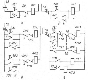
Rice. Motor control schemes as a function of travel with limit switches: a and b — motor shutdown at the end of the movement of the mechanism, c — with limitation of the movement of the mechanism, d — cyclic movement with time delay of the end positions
The control circuit of Fig. c provides for the movement of the mechanism along a path limited by two limit switches SQ1 and SQ2, and the work can be carried out both in discrete and continuous strokes. In the first case, the mechanism starts to move forward when the button SB1 is pressed and moves until it presses the limit switch SQ1. To remove the mechanism from this position, press the SB2 button.
Opening contacts KM2 and KM1 in the circuits of coils KM1 and KM2 are used for blocking.
For the cyclic operation of the mechanism with different time delays in the end positions, the diagram in fig. d. When starting the engine forward, the start button SB1 turns on the time relay KT1 and opens its contact in the circuit of the coil of the contactor KM2. Movement continues until the trip switch SQ is actuated, which opens the circuit of the contactor coil KM1 and closes the SQ contact mechanically connected to it. But the reversal does not happen immediately, because the opening contact KT1 is still open.
The time relay KT1, disconnected from the contact KM1, counts down the set time delay and turns on the coil of the contactor KM2, turning the motor. Through the contact of the closing block KM2, the time relay KT2 turns on and breaks the circuit of the coil KM1 with the contact KT2. The electric motor turns on and moves the mechanism until the limit switch is actuated, after which the cycle repeats in the same order.
If, according to the operating conditions, a time delay is required in only one end position, then one time relay and its opening contact are switched off in the control circuit.