How to reduce non-sinusoidal voltage
 A number of electricity consumers have a non-linear dependence of current consumption on the applied voltage, due to which they consume a non-sinusoidal current from the network... This current flowing from the system through the elements of the network causes a non-sinusoidal voltage drop in them, which "superimposes" the applied voltage and distorts. Sinusoidal voltage distortion occurs at all nodes from the power supply to the nonlinear electrical receiver.
The sources of harmonic distortion are:
-
arc furnaces for steel production,
-
valve converters,
-
transformers with non-linear volt-ampere characteristics,
-
frequency converters,
-
induction furnaces,
-
rotating electrical machines,
-
powered by valve converters,
-
television receivers,
-
fluorescent lamps,
-
mercury lamps.
The last three groups are characterized by a low level of harmonic distortion of individual receivers, but a large number of them determine a significant level of harmonics even in high-voltage networks.
See also: Sources of harmonics in electrical networks and Reasons for the appearance of higher harmonics in modern power systems
Ways to reduce the non-sinusoidal voltage can be divided into three groups:
a) chain solutions: distribution of non-linear loads on a separate bus system, distribution of loads in different units of the SES with the connection of electric motors in parallel with them, grouping of converters according to the phase multiplication scheme, connection of the load to a higher power system ,
b) use of filtering devices, inclusion in parallel of the load of narrowband resonance filters, inclusion of filter-compensating devices (FCD);
c) the use of special equipment characterized by a reduced level of generation of higher harmonics, use of "unsaturated" transformers, use of multiphase converters with improved energy characteristics.
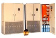 Development elemental basis of power electronics and new methods of high-frequency modulation led to the creation in the 1970s of a new class of devices, improving the quality of electricity – active filters (AF)... Immediately arose the classification of active filters into series and parallel, as well as current and voltage sources, which led to four main circuits.
Each of the four structures (Fig. 1. 6) determines the filter circuit at the operating frequency: the switches in the converter and the type of switches themselves (two-way or one-way switch). As an energy storage device in a converter that serves as a current source (Fig. 1.a, d), it is used inductance, and in the converter, which serves as a voltage source (Fig. 1.b, c), capacitance is used.
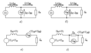
Figure 1.The main types of active filters: a — parallel current source; b — parallel voltage source; c — series voltage source; d — series current source
It is known that the resistance of the filter Z at frequency w is equal to

When ХL = ХC or wL = (1 / wC) at frequency w, voltage resonance, which means that the resistance of the filter for the harmonic and voltage component with frequency w is equal to zero. In this case, the harmonic components with frequency w will be absorbed by the filter and will not penetrate the network. The principle of designing resonant filters is based on this phenomenon.
In networks with non-linear loads, as a rule, harmonics of the canonical series arise, the order number of which is ν 3, 5, 7,. … ..
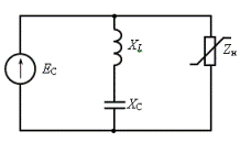
Figure 2. Equivalent circuit of a power resonance filter
Taking into account that XLν = ХL, ХCv = (XC / ν), where XL and Xc are the resistances of the reactor and the capacitor bank at the fundamental frequency, we obtain:

A filter that, in addition to filtering harmonics, will generate reactive power, and compensates for network power loss and voltage, is called compensation filter (PKU).
If a device, in addition to filtering higher harmonics, performs the functions of voltage balancing, then such a device is called filter balancing (FSU)... Structurally, FSUs are an asymmetric filter connected to the line voltage of the network. The choice of line voltage to which the FSU filter circuits are connected, as well as the power ratios of the capacitors included in the filter phases, are determined by the voltage balancing conditions.
It follows from the above that devices such as PKU and FSU act simultaneously on several power quality indicators (non-sinusoidal, asymmetry, voltage deviation). Such devices for improving the quality of electrical energy are called multifunctional optimizing devices (MOU).
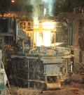 The expediency in the development of such devices arose due to the fact that suddenly variable loads of the type arc steel furnaces cause simultaneous voltage distortion for a number of indicators. The use of MOU provides an opportunity to comprehensively solve the problem of ensuring the quality of electricity, i.e. simultaneously for several indicators.
The category of such devices includes high-speed static reactive power sources (IRM).
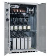 According to the regulation principle of reactive power, IRM can be divided into two groups: high-speed static reactive power sources of direct compensation, high-speed static reactive power sources of indirect compensation... The structures of IRM are shown in Figure 3, a, b, respectively . Such devices, which have a high response speed, can reduce voltage fluctuations. Stepwise adjustment and the presence of filters provide balancing and reduction of higher harmonic levels.
In fig. 3, a direct compensation circuit is presented where the "controlled" reactive power source is switched by means of thyristors capacitor bank. The battery has several sections and allows you to discretely vary the reactive power generated. In fig. 3b, the IRM power is varied by adjusting the reactor. With this control method, the reactor consumes excess reactive power generated by the filters.Therefore, the method is called indirect compensation.
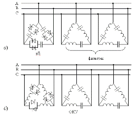
Figure 3. Block diagrams of a multifunctional IRM with direct (a) and indirect (b) compensation
Indirect compensation has two main disadvantages: absorbing the excess power causes additional losses, and changing the reactor power using the valve control angle leads to additional generation of higher harmonics.
