Increasing the power factor in sinusoidal current circuits
 Most modern consumers of electrical energy have an inductive nature of the load, whose currents lag behind the source voltage. So for induction motors, transformers, welding machines and other reactive current is needed to create a rotating magnetic field in electrical machines and an alternating magnetic flux in transformers.
The active power of such consumers at the given values of current and voltage depends on cosφ:
P = UICosφ, I = P / UCosφ
A decrease in power factor leads to an increase in current.
Cosine phi it is particularly greatly reduced when motors and transformers are idling or under heavy load. If the network has reactive current, the power of the generator, transformer substations and networks is not fully utilized. As cosφ decreases, they increase significantly loss of energy for heating wires and coils of electrical devices.
 For example, if the real power remains constant, it is provided with a current of 100 A at cosφ= 1, then with decreasing cosφ to 0.8 and the same power, the current in the network increases by 1.25 times (I = Inetwork x cosφ , Azac = Aza / cosφ ).
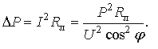
Losses on the wires of the heating network and windings of a generator (transformer) Pload = I2nets x Rnets are proportional to the square of the current, that is, they increase by 1.252 = 1.56 times.
At cosφ= 0.5, the current in the network with the same active power is equal to 100 / 0.5 = 200 A, and the losses in the network increase by 4 times (!). It's growing network voltage losseswhich disrupts the normal operation of other users.
The user's meter in all cases reports the same amount of consumed active energy per unit of time, but in the second case the generator feeds the network with a current that is 2 times greater than that in the first. The generator load (thermal mode) is determined not by the active power of consumers, but by the total power in kilovolt-amperes, that is, the product of the voltage by amperageflowing through the coils.
If we denote the resistance of the wires of the line Rl, then the power loss in it can be determined as follows:
Therefore, the larger the user, the less power losses in the line and the cheaper the transmission of electricity.
The power factor shows how the rated power of the source is used. So, to supply the receiver 1000 kW at φ= 0.5 the generator power should be S = P / cosφ = 1000 / 0.5 = 2000 kVA, and at cosφ = 1 C = 1000 kVA.
Therefore, increasing the power factor increases the power utilization of the generators.
To increase the power factor (cosφ) electrical installations are used reactive power compensation.
Increasing the power factor (reducing the angle φ — phase shift of current and voltage) can be achieved in the following ways:
1) replacement of lightly loaded engines with engines of lower power,
2) under voltage
3) disconnection of idle motors and transformers,
4) the inclusion of special compensating devices in the network, which are generators of the leading (capacitive) current.
For this purpose, synchronous compensators — synchronous overexcited electric motors — are specially installed at powerful regional substations.
 Synchronous compensators
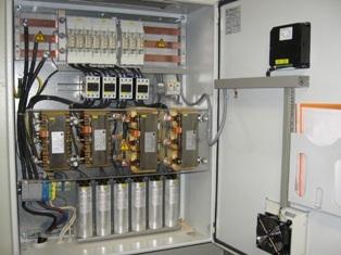
To increase the efficiency of power plants, the most commonly used capacitor banks are connected in parallel with the inductive load (Fig. 2 a).
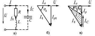
Rice. 2 Switching on capacitors for reactive power compensation: a — circuit, b, c — vector diagrams
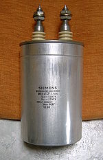
To compensate cosφ in electrical installations up to several hundred kVA they are used cosine capacitors… They are produced for voltages from 0.22 to 10 kV.
The capacity of the capacitor required to increase cosφ from the existing value cosφ1 to the required cosφ2 can be determined from the diagram (Fig. 2 b, c).
 When constructing a vector diagram, the source voltage vector is taken as the initial vector. If the load is inductive, then the current vector Az1 lags behind the angle of the voltage vector φ1Aza coincides in direction with the voltage, the reactive component of the current Azp lags behind it by 90 ° (Fig. 2 b).
After connecting the capacitor bank to the user, the current Az is determined as a geometric sum of vectors Az1 and Az° C... In this case, the capacitive current vector precedes the voltage vector by 90 ° (Fig. 2, c). This shows the vector diagram φ2 <φ1, i.e. after switching on the capacitor, the power factor increases from cosφ1 to cosφ2
The capacity of a capacitor can be calculated using a vector diagram of currents (Fig. 2 c) Ic = azp1 — Azr = Aza tgφ1 — Aza tgφ2 = ωCU
Given that P = UI, we write the capacitance of the capacitor C = (I / ωU) NS (tgφ1 — tgφ2) = (P / ωU2) NS (tgφ1 — tgφ2).
In practice, the power factor is usually increased not to 1.0, but to 0.90 — 0.95, since full compensation requires additional installation of capacitors, which is often not economically justified.