Protection of rural distribution networks with a voltage of 10 kV
According to the requirements, the first stage of protection is carried out in the form of current interruption, and the second in the form of overcurrent protection (overcurrent protection) with a current-dependent delay characteristic... Current interruption is carried out on the RTM type relay and overcurrent protection on the RTV relay . RTM and RTV relays are direct-acting relays that are both measuring and executive devices, acting directly on the breaker drive.
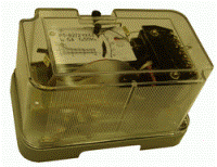 Overcurrent protection of the RTB type relay is still widely used air lines 10 kV.
Of the electromechanical relays, the most accurate are the RT-85 type induction relay with a limited time-dependent actuation characteristic. These relays consist of three elements: inductive, electromagnetic momentary (current interrupt) and index. Overcurrent protection circuit for RT-85 type relays shown in fig. 1.
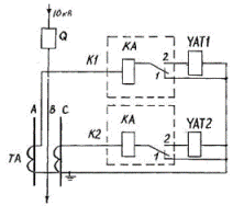 Rice. 1. Scheme of overcurrent current protection for relay type PT-85: K.1, K.2-current relay of type PT-85; Q — breaker in the 10 kV line; TA — current transformer.
The RT-85 relay has special reinforced switching contacts.Under normal operating conditions, the break contacts 1 of the relay KA1 and KA2 are closed and manipulate the cut-off electromagnets UAT1 and UAT2, and the closing contacts 2 of these relays are open, so that the current through the cut-off electromagnets does not pass. In the event of a short circuit on the line, the time-delayed relay is activated, its contacts are switched, that is, contact 2 first closes, and then contact 1 opens. The release solenoid - UAT is bypassed by the full current of the secondary winding of the current transformer and at a sufficient value of current it is actuated by acting on the actuating mechanism of the circuit breaker drive and the circuit breaker is tripped. These circuits are called circuits with tripping solenoid.
To increase the sensitivity of two-phase short-circuit protection behind the 10 kV transformer with A / Y winding connection diagram, an additional third relay RT-85 is installed.
Maximum current protection type TZVR
Semiconductor maximum (current protection type TZVR is designed to protect distribution lines 6-10 kV from all types of short circuits. / 10 kV of all types, in the cabinets of the distribution points of sectioning and redundancy, where when changing the mode of operation of the line , you don't need to choose the current and time protection settings.
TZVR protection makes it possible to combine a large number of sequentially installed protection sets and, most valuable, with virtually no time delay accumulation.
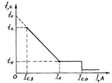 Rice. 2. Ampere-second characteristic of protection type TZVR
The TZVR device contains a single-system overcurrent protection with a limited dependence, widely adjustable ampere-second characteristic, in which the action time in the dependent part is linearly dependent on the short-circuit breaking current and current, and also contains an indicator relay, a circuit breaker, a disconnect electromagnet, current block for electromagnet and elements for operational testing of the whole device.
In the independent part of the characteristic, the protection time can be smoothly adjusted from 0.1-0.2 to 0.4 s. Due to the possibility of changing in a wide range the time-current characteristics of the TZVR device, the coordination of sets of protections installed in series along the line is carried out without accumulating a time delay at the head of the line.
The protection has the same sensitivity to three-phase and two-phase short circuit at one point, i.e. its sensitivity is 2 / √3 times higher than that of MTZ with RTV and RT-85 relays connected to phase currents.
The operating current of the TZVR device is infinitely adjustable from 2.5 to 40A. The interrupting tripping current can be adjusted from twice the maximum tripping current of the protection to the complete withdrawal of the tripping current from operation.
The main benefits of TZVR protection include:
-
ability to coordinate a large number of adjacent defenses without accumulating time delay;
-
provides the same sensitivity for three-phase and two-phase short circuits of the protected line;
-
contains besides MTZ and current cutoff;
-
has an autonomous source of operating current — a power supply unit that ensures the operation of the protection and the disconnecting electromagnetic switch.
The device is connected to connections equipped with two current transformers.
Semiconductor device for switching settings for overcurrent protection, type UPS
On cut lines with network redundancy, when changing the power supply mode of the lines, the direction of flow of the load currents changes and short circuit. Therefore, to ensure the necessary sensitivity and selectivity of the protective devices, it is necessary to use directed overcurrent (NMTZ) or distance protection at the points of sectioning and redundancy.
Applied NMTZ consisting of current relays such as firing bodies, time relay and power direction relays have the following disadvantages: the presence of a «dead zone» in which the power direction relay fails due to a decrease in the voltage measured by the voltage transformer due to a short circuit in this area (since the power direction relay is triggered by the value of the product of current and voltage), the need for qualified personnel servicing these devices; it is also possible to note as a disadvantage the large dimensions of the relay RT-85, the power direction relay type RBM-171 and others, which are difficult to place in the relay compartment of the KRUN switchgear.
The UPZS device consists of two semiconductor time relays with delay adjustment limits from 8 to 80 s and triggered when the value of the controlled voltage disappears or falls below 20% of the nominal.
The device of type UPZS is intended for switching overcurrent protection sets at separation points of 10 kV lines with network redundancy, as well as as local automatic transfer switching transformer substations 10 / 0.4 kV and network ATS in 10 kV lines network backup points.
The device can be used in automation schemes as a time relay, for example, it can be used for remote control of circuit breakers installed in distribution networks, turning off the main switch for a certain time and fixing the duration of the pause in the supply voltage 10 kV. run automatic control circuits to melt ice switches, etc.
Using the UPZS device, for example, local ATS can be carried out in closed transformer substations 10 / 0.4 kV with a KSO-272 camera at the backup input, where a load switch is used at the working input and an oil switch in the KSO-272 camera at the backup .
Voltage control is performed on the side of the low voltage busbars of the 10 / 0.4 kV transformer.
In the event of a 0.4 kV bus voltage interruption, the ATS device gives a command to turn off the working input and turn on the backup one.
To perform a network switch for automatic transfer, closed transformer substations are equipped with two cameras KSO-272 with oil circuit breakers and one set of protection type KRZA-S.
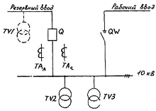
Rice. 3. Scheme ZTP -10 / 0.4 kV: TV — voltage transformer TA — current transformer; Q — 10 kV breaker; QW — switch
When choosing the settings for the operation of the UPS device in the protection switching mode, the delay time should be greater than the time without current of the automatic reclosing of the main switch of the 10 kV line and less time for the operation of the mains ATS.
Double acting directional overcurrent protection device, type LTZ
The protection is designed for 6-20 kV sectioned lines with grid redundancy and double-sided power supply.This device can also be used to protect lines with unidirectional power supply in case of phase-phase short circuit and power transformers with a voltage of 6-35 kV... LTZ protection can installation in KRUN, on tires and on panels relay protection of substations, at points of separation and excess of cut lines.
The peculiarity of the LTZ device is that, depending on the direction of the power transmitted through the line, there is an automatic switch to the specified settings for the operation of the second stage in terms of current and time.
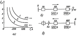 Rice. 4. Selectivity curves (a) of LTZ protection, depending on the direction of power (current), when the network is 10 kV from source A (b) or B (c): GV, SV, AVR — head, section and ATS point 10 kV switches; RTV — time-delay current relay.
The body for the direction of the supply power is in the triggered position when the line is fed from substation A. In this case, the LTZ device has higher current settings and response than the protection in the ATS (characteristics 1 and 3 in Fig. 4, a). This setting corresponds to selective operation of the short-circuit protection at point K1.
The LTZ device automatically switches to lower current and response time settings (characteristic 2 in Fig. 4, a) when the line operation mode changes and when fed from substation B (Fig. 4, c). In this case, the pointer does not work. LTZ protection in the event of a short circuit at point K.2, it will work earlier than the protection at point ATS (characteristic 3).
The advantages of the LTZ device made on the elements of radio electronics include the absence of a «dead zone», current-dependent characteristics, the possibility of accelerating the protection action if short circuits, since the voltage drops so much that the power direction element does not can remain in the triggered state.
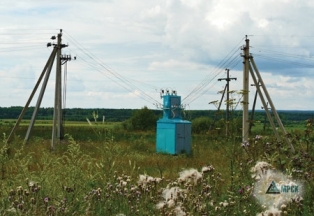 Semiconductor device for complete relay protection and automation of 10 kV line section points, type KRZA-S
The KRZA-S device is a semiconductor remote protection with a linear dependence on the value of the resistance of the terminals of the response time characteristic of the device, thus ensuring selectivity of the protection at points of sections of 10 kV lines with bidirectional supply.
The KRZA-S set is designed to protect 10 kV split distribution lines with mains shorting from all types of phase-to-phase short circuits and to automatically reclose 10 kV lines... The device can be used at any existing split points, as well as on lines with mains redundantly, as well as on radial lines, in case the overcurrent protection does not meet the sensitivity and selectivity requirements.
The KRZA-S device consists of a relay device representing a single-system two-stage distance protection of the first stage - distance interruption with a response time totc and of the second stage - distance protection, the response time of which increases in proportion to the increase in resistance in the terminals of the device and the double-acting AR device (similar to the APV-2P discussed below) with a self-contained power supply unit for the breaker trip solenoid.The device is equipped with operational functionality testing facilities.
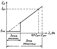 Rice 5. Protective characteristic of the device type KRZA-S
When using this set of protection and automation at breakpoints, no additional installation of other equipment is required. To connect the device, you need two current transformers and two single-phase or one three-phase voltage transformer in the switchgear.
The KRZA-S device has a number of advantages over similar ones:
-
hypersensitivity;
-
provides selectivity of protective action without accumulating time delay by using a single set of protection that does not require switching when changing the mode of operation of a sectional line with bidirectional supply;
-
stability of action zones and shorter response time, simplicity of the design of the automatic closing device with adjustable time of pauses without current of the first and second cycles.
